Connectors are lines that link different flowchart shapes (or any shapes you place within your Microsoft Office documents). They are different from conventional lines because connectors, as the name implies, stay connected to the shapes they are linked to. Move any "connected" shape in PowerPoint and Excel versions of Office 2013, and the connectors move and reorient with the shapes automatically. Unfortunately, this does not work the same way in Word 2013. Let us explore further in this tutorial.
Remember: Draw your connectors only after the shapes they are going to link are placed. You'll need at least two flowchart shapes to start with. If you draw your connector before the shapes are in place, your connector will end up being a mere line with no "connects".
Follow these steps to connect two flowchart shapes:
- Insert two flowchart shapes, as shown in Figure 1.
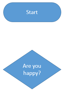
Figure 1: Text that makes you happy?
Note: In
Figure 1, the first oval shape with the
Start text is a
Terminator in flowchart parlance whereas the second diamond shape with the
Are you happy? text is a
Decision shape. Learn more about flowchart terminology in our
Flowchart Symbols: What They Represent? tutorial.
- Now, access the Insert tab of the Ribbon, and click the Shapes button (this works in Word, Excel, and PowerPoint). Doing so brings up the Shapes drop-down gallery. Select the Arrow shape, which is second shape within the Lines category as you can see in Figure 2, below. This shape is a connector that has an arrowhead at one end.
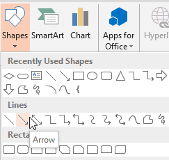
Figure 2: Choose a connector with an arrowhead - We need the arrowhead end of the connector to be “connected” to your Decision shape, and the non-arrowhead end will emanate from the Terminator shape.
- When you select the required connector, the cursor changes into a crosshair. Notice that as you move the cursor near to the Terminator shape, you'll find several blue round handles highlighted on the shape (see top shape in Figure 3). Click on any of these blue handles to establish one end (the end without an arrowhead) of your connector.
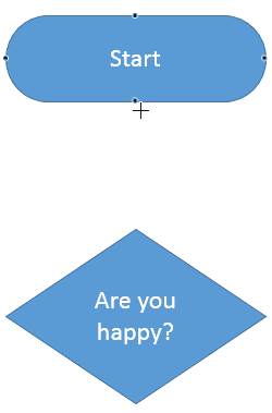
Figure 3: Blue round handles highlighted on the Terminator shape - Move the cursor toward the shape you want to connect (the Decision shape shown in Figure 4). Click again on any of the blue round handles on the second shape to create the connector between two shapes. Note that the arrowhead of the connector will show on this end.
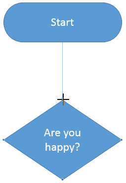
Figure 4: Connect to other shape - This creates a connector, as shown in Figure 5. Select any shape, and click on the arrow keys on your keyboard to nudge the shape. You will find that the connector reorients according to the new position of the shape.
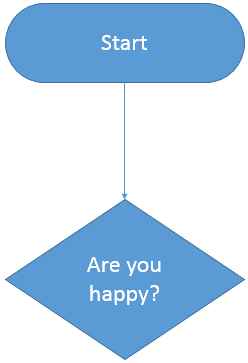
Figure 5: Shapes connected to each other
- Note: If your connector is indeed linked to a shape, the end of the connector line that is connected to the shape displays a green circle (see top shape in Figure 6). If it does not get linked, you will see a white square (see shape at the bottom in Figure 6) when you select the connector. It is important to understand that mere "touching" of a connector's end to a shape or slide object does not indicate that it has been linked to that shape or slide object. When you see a green circle on both the ends of the connector, only then you can be assured that the ends are connected.
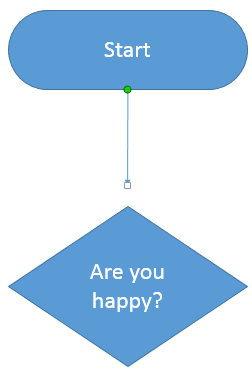
Figure 6: Connectors may or may not be linked properly
- Save your presentation often.


