While PowerPoint lets you attach a connector to any slide object, these
connectors can only be attached to wherever you see an anchor point on the slide object. Figure 1 below shows anchor points for the triangle
shape. Notice that the anchor points are small, red squares. Most of the time, the location of these anchor points may work well for you. However, in certain
scenarios, you may want additional anchor points at a particular location.
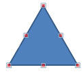
Figure 1: Red anchor points indicate where connectors can be attached
The good news is that you can add new anchor points for shapes and
text boxes using the technique explained on this page. For
text placeholders though, you cannot add new anchor points.
If you need more anchor points for pictures, it is suggested that you use any shape as a container for a
picture fill, and add anchor points as required
for the container shape. We have now established that you can add new anchor points for shapes (and text boxes) so that your connectors can be linked to
exactly where you want them to be! Follow these steps in PowerPoint 2010 for Windows to explore more:
- Insert two shapes on a new slide. For example, we placed two shapes: a
triangle and a circle. We then linked them with a connector, as shown in
Figure 2 below.
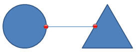
Figure 2: Connector connecting a circle and a triangle- Notice that the connector attaches to an anchor point on the left edge of the triangle (refer to Figure 2, above). However, we want
to attach the connector's right end to a lower position on the triangle—but not as low as its base. We tried to do that and ended up with something you can
see in Figure 3, below. Notice that the triangle end of the connector is no longer anchored—rather it is a "disconnected" connector,
as indicated by the white circle.
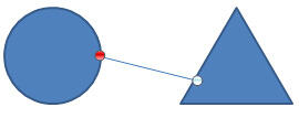
Figure 3: Connector disconnected from the triangle
Note: If your connector gets linked to a slide object, the end of the connector line displays a red circle (see the example on the left in
Figure 3). If it does not get linked, you will see a white circle (see example on the right in Figure 3). It is important to
understand that mere "touching" of a connector's end to a shape or slide object does not indicate that it has been linked to that shape or slide object.
When you see a red circle on both of connector's ends, only then you can be assured that the ends are connected.
- To alter this, we need to add a new anchor point on the triangle at the exact position where we want to link the connector. To do this task,
select the triangle. Then, carefully right-click the triangle and choose the
Edit Points option in the resultant contextual menu, as shown in Figure 4.
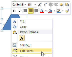
Figure 4: Edit Points option selected- Notice that the triangle shows three points (vertexes) on its
corners, as shown in Figure 5.
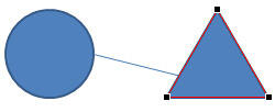
Figure 5: Triangle showing three vertexes on its corners- To add a new point, carefully hover your cursor over the outline
of the triangle at the position you want. Notice that the cursor changes to a combo square-crosshair at this point of time, as shown in Figure 6
(highlighted in red).
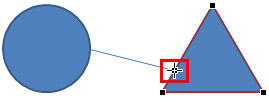
Figure 6: Cursor changed to a combo square-crosshair- Carefully right-click at the same position. From the resultant contextual menu, choose the Add Point option, as shown in
Figure 7.
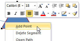
Figure 7: Add Point option selected- This adds a new point on the triangle's outline as visible in Figure 8.

Figure 8: New point added to the outline of the triangle- Once the new point is added to the triangle at the required position, select the connector connecting the circle. Then, click on the right-edge
of the connector (white circle) and pull it close to the position on the triangle where you added the new point. Notice that now this new point also functions
as an anchor point for the connector, as shown in Figure 9.
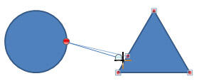
Figure 9: New point (vertex) added to the triangle functions as an anchor point
Note: After you add a new point (vertex) to the triangle in Edit Points mode, you will end up with only vertex points being
anchor points. All non-vertex points will no longer show as anchor points. Compare triangles in Figure 9, below and Figure 1,
earlier on this page. In Figure 9, only vertex points show as anchor points but in Figure 1, there are several other anchor
points as well.
- Pull the connector to the new anchor point to link it to the triangle. Notice how the right-end of the connector in Figure 10
now shows a red circle, indicating that this is now a linked connector. Compare Figures 3 and 10.
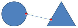
Figure 10: Connector connected to the new anchor point- Save your presentation often.


